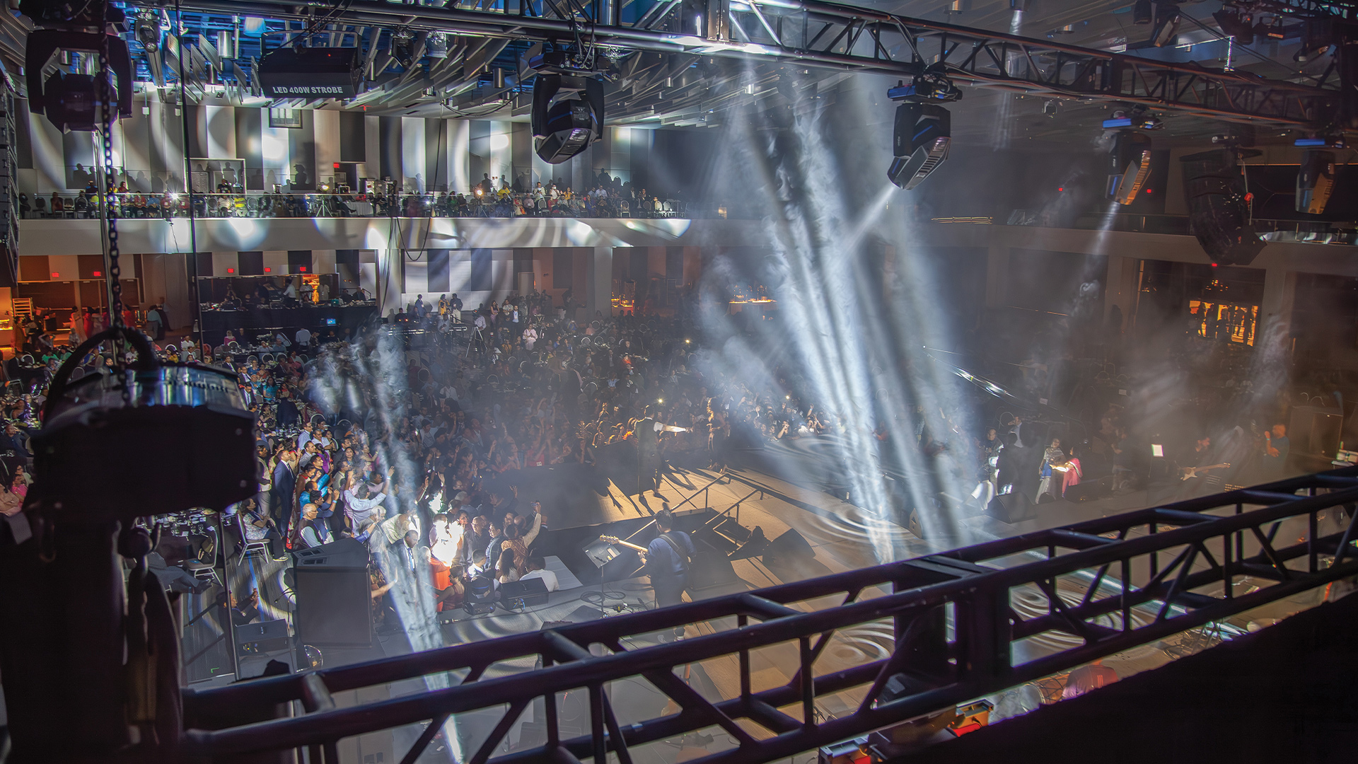
A radio frequency scan of a venue before a large event is one of the most critical — and most frequently under-resourced — steps in professional wireless audio deployment. In a major metropolitan event venue, the RF environment is a chaotic spectacle of overlapping signals: cellular infrastructure from multiple carriers, broadcast television transmissions, adjacent event wireless systems, temporary cellular deployments for event data services, emergency services radio, and the residual RF garbage of dozens of wireless devices operating without coordination. Deploying a professional wireless microphone and IEM system into this environment without first mapping the available frequency spectrum is equivalent to driving at night without headlights — you may arrive safely, but the risk is entirely unnecessary and the consequences of failure are immediate.
The Scan Hardware You Need
A thorough RF scan requires a dedicated spectrum analyzer — a device that displays signal strength across a defined frequency range in real time. The professional standard is the Shure Axient Digital AD610 ShowLink Access Point combined with Wireless Workbench 6 software, which automates frequency coordination calculation based on scan data. For standalone scanning, the RF Explorer — a compact and affordable USB spectrum analyzer — is widely used by engineers who need a portable scanning tool without the full Shure ecosystem. Kaltman Creations RF Shark provides a more sophisticated scanning and analysis platform suitable for complex multi-system deployments. At minimum, the scanning antenna must be omnidirectional and positioned at the point in the venue where wireless transmitters will be operating — scanning from FOH position does not reveal the RF environment at stage position where the transmitters will be.
Scanning Methodology: Time and Position
The RF environment in a busy event city is not static. Cellular load patterns shift throughout the day as commuter patterns change; temporary cellular deployments for event data services come online during show setup; adjacent venue events begin their own wireless system deployments in the hours before the show. A scan conducted at 9am during load-in may look completely different from the RF environment at 8pm when the show begins. Best practice is to conduct multiple scans: an initial scan during early load-in to establish the baseline, a second scan at maximum expected RF congestion (approximately 2 hours before show time, when all local wireless systems are active), and a final scan immediately before wireless system power-up. Each scan should run for a minimum of five minutes per frequency block to capture intermittent signals that don’t appear on instantaneous measurements.
Frequency Coordination: The Math Behind Clean Wireless
Once scan data reveals the available frequency spectrum, intermodulation (IM) distortion calculations determine which specific frequencies can be used simultaneously without interfering with each other. Intermodulation occurs when two or more RF signals mix in a non-linear system (such as a receiver’s front end) and produce sum and difference frequencies that fall on a third channel’s frequency, causing interference that sounds like noise, dropouts, or signal instability. Wireless Workbench, IAS (Intermodulation Analysis System), and Sennheiser WSM all perform automated IM calculations to identify frequency sets where third, fifth, and seventh-order intermodulation products don’t land on any active channel. The output is a list of compatible frequencies that can be programmed into transmitters and receivers with confidence that they won’t interfere with each other under normal operating conditions.
Urban-Specific Challenges: The LTE/5G Factor
In major cities, the most significant driver of UHF spectrum congestion in recent years has been the expansion of LTE and 5G cellular services. The 600 MHz band (TV Band 71) refarmed by the FCC in the US for T-Mobile’s 5G deployment now occupies spectrum that was previously used by professional wireless audio — forcing an industry-wide frequency shift that continues to create problems for productions using older wireless equipment not designed for post-repack spectrum. In European cities, 5G deployment in the 700MHz band has created similar issues. The practical consequence is that the usable UHF window for professional wireless in dense urban environments has narrowed significantly, and digital wireless systems — Shure Axient Digital, Sennheiser Digital 6000, Lectrosonics DSQD — with their superior spectral efficiency and interference rejection become not just preferable but often operationally necessary.
Antenna Systems and Signal Distribution
Even perfectly coordinated frequencies deliver poor results if the antenna system is poorly designed. On large productions, antenna distribution systems — RF combiners and splitters from Shure, Lectrosonics, and RF Venue — allow multiple receivers to share a single antenna installation, reducing antenna density on stage and providing more consistent RF coverage across the performance area. Active directional antennas like the Shure UA874WB and RF Venue DIVERSITY FIN improve signal reception in congested environments by providing directional gain and discrimination against interference from directions outside the main lobe. Antenna cable run length must account for signal loss — every meter of coaxial cable attenuates the RF signal, and long runs must be compensated with in-line amplifiers rated for the specific frequency range in use.
